Voltage Divider Calculator — Enter Any Three, Solve the Fourth
Inputs
Results
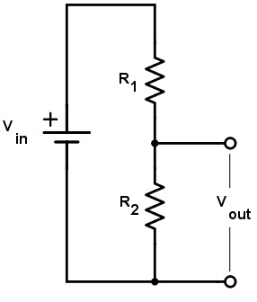
Diagram
Formulas
Ideal (no load):
$$ V_{out} = V_{in} \cdot \frac{R_2}{R_1 + R_2} $$
Rearrangements:
- Given \(V_{in}, V_{out}, R_2\): \( R_1 = R_2 \left(\frac{V_{in}}{V_{out}} - 1\right) \)
- Given \(V_{in}, V_{out}, R_1\): \( R_2 = R_1 \cdot \frac{V_{out}}{V_{in}-V_{out}} \)
- Given \(V_{out}, R_1, R_2\): \( V_{in} = V_{out} \cdot \frac{R_1 + R_2}{R_2} \)
Divider current (no load): \( I_{div} = \dfrac{V_{in}}{R_1 + R_2} \). Power: \( P_1 = I_{div}^2 R_1 \), \( P_2 = I_{div}^2 R_2 \).
Voltage Divider Tips & Best Practices
- Choose sensible resistor values. Large resistances reduce quiescent current but increase noise and sensitivity to bias/leakage. 10–200 kΩ total is a practical range for MCU inputs.
- Check the load. Any device on Vout is in parallel with R2. Effective lower leg is \(R_2 \parallel R_L\), which pulls Vout down.
- Mind power dissipation. Verify \(I_{div}\) and each resistor’s wattage.
- Buffer when needed. Use an op-amp follower or a proper regulator if the load is low.
- Tolerances & tempco. Prefer 1% (or better) resistors; ppm/°C matters for precision.
- Bandwidth. High-value dividers + input capacitance form an RC filter.
Rule of thumb: make divider current ≳10× the input bias current of what you’re driving, or buffer the node.
Understanding the Voltage Divider Concept
A voltage divider is one of the most fundamental building blocks in electronics. It is created by connecting two resistors in series across a voltage supply and taking the output from the junction between them. The ratio of the two resistances determines how the input voltage (Vin) is divided into a smaller output voltage (Vout). The simplicity of this circuit makes it an essential tool for engineers, hobbyists, and students learning about circuits.
The key idea is proportionality: the output voltage depends on the fraction of total resistance contributed by the lower resistor (R2). Mathematically, this is expressed as \( V_{out} = V_{in} \times \dfrac{R2}{R1 + R2} \). This formula highlights why the voltage divider is so flexible—by choosing appropriate values for R1 and R2, you can generate almost any intermediate voltage between zero and the input supply.
In practice, voltage dividers are used in many applications:
- Signal scaling: When an input signal is too large for an analog-to-digital converter (ADC) or microcontroller pin, a divider reduces it safely into range.
- Reference levels: Voltage dividers often provide bias voltages for transistors or op-amp circuits.
- Sensor interfacing: Many resistive sensors (like thermistors or photoresistors) form part of a divider to translate changing resistance into a measurable voltage.
- Audio and communication systems: Dividers can attenuate signals before amplification or further processing.
While useful, voltage dividers have limitations. They are not suitable for supplying significant power to a load because the output voltage drops if the connected device draws current. That is why dividers are best for measurement and signal purposes rather than powering circuits. To overcome this, designers often buffer the output with an operational amplifier or use a dedicated voltage regulator.
Understanding voltage dividers not only helps with practical circuit design but also builds intuition about how resistance, current, and voltage interact. They serve as a stepping stone toward mastering more complex networks, Thevenin equivalents, and real-world power management. Whether you are working on robotics, audio electronics, or embedded systems, the voltage divider is a concept you will use repeatedly.